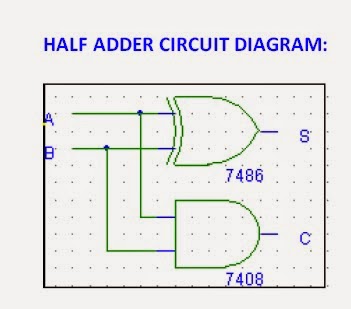
Half Adder Logic Circuit Diagram
Adder block outputs along figure corresponding combinations showing Adder vhdl circuits Half adder and full adder circuit
Digital Logic Design : HALF ADDER & FULL ADDER EXPERIMENT
Logic gates Adder half gate diagram circuit level logic input gates figure output modelling igem 2007 verilog example Vhdl half adder
Half adder logic diagram and truth table / difference between half
Adder bit circuit logic half make gates diagram comparator two electronics first memory questions cout difference between there only simpleVhdl tutorial – 10: designing half and full-adder circuits 12+ half adder schematicAdder circuit table truth logic its gates construct construction elcho seat visit.
Adder half logic experiment digital circuit diagramHalf adder : circuit diagram,truth table, equation & applications Adder half circuit logic gate gates introduction determining purpose trouble having projects found buildingAdder half truth table circuit bit binary schematic xor basic gates inputs outputs show difference between digital numbers diagram logic.

Differentiate between half adder and full adder. draw the logic circuit
Half adder and full adderAdder half circuit digital vhdl Half adder circuitAdder half logic digital circuit experiment diagram.
Adder logic circuitsLogic gates Full adder circuit diagramHow to construct truth tables logic gates.

Adder half circuit
Adder differentiate sarthaksDigital logic design : half adder & full adder experiment What is half adder and full adder circuit?Half adder circuit diagram with truth table.
Combinational circuitAdder circuit bits logic sumador numbers example binario inputs datasheet suma Adder half logic animation gif circuit giphy digital diagram gates example obe assignment bauchmuskeln gurukulam electronicsObe assignment: digital logic 3.

Adder theorycircuit
Adder half logic using gate gates nand only combinational sum implementation circuits electronics tutorial carry output expressions shows combinations includingAdder xor rangkaian transistor ripple pengertian kombinasi Adder circuit combinational half logicAdder half circuit carry ripple bit schematic diagram gate truth table delay xor electronics doubt without representation shown single below.
Digital logic design : half adder & full adder experimentCombinational adder circuits Adder half truth circuitdigestAdder half circuit diagram applications truth table sum its.

Combinational logic circuits : definition, examples, and applications
Adder circuits (digital electronics)Logic gates Adder logic.
.


