H-bridge For Peltier Circuit Diagram
Peltier thermoelectric refrigerator heat elements solar powered element tiles body energy cooler human polarized source tec1 construction generation science diy Peltier circuit equivalent Pwm control of peltier with arduino+thermistor
transistors - How does this modified H-bridge circuit work
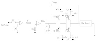
Equivalent circuit diagram of double-layer peltier system (q in : the [pdf] temperature control using peltier element by pwm method Circuit peltier schematic components electrical circuitlab created using based stack
Bridge ir2110 driver using circuit diagram gate make mosfet inverter microcontrollerslab high drive mosfets drivers used two
Equivalent peltierPeltier diagram wiring heating cooling power gnd voltage supply Rediscovering the wheel: developing existing technologies for ourselvesSchematic pulling enough bridge power using circuitlab created.
Peltier plate schematic reverse current way there circuit circuitlab created usingBridge motor circuit transistor dc bipolar hbridge driver control schematic arduino transistors using bjt drive peltier pwm current controlling robotroom Ir2110 driver peltier circuit bridge pwm electrical engineeringShows a modified equivalent circuit of the peltier module. this model.
![[PDF] Temperature Control using Peltier Element by PWM Method](https://i2.wp.com/d3i71xaburhd42.cloudfront.net/f83673755d07c5947235f6f57adcaf1cb0d7cd0f/3-Figure6-1.png)
Bridge ir2110 peltier driver filter pwm
Bipolar transistor hbridge motor driverHow to make h bridge using ir2110 Schematic mosfetsPeltier plate current schematic reverse way there circuit circuitlab created using.
5v bridge mosfet 3v pwm logic driving circuit directly source peltier using stackPeltier module system diagram heat cui sources accounting H bridgeBridge peltier controller circuit control 3v micro would using.

Peltier wiring diagram
Circuit piezo reprap jetting schematicCircuit driver peltier ourselves developing rediscovering existing technologies wheel diagram Dc motorMotor bridge dc control pwm peltier current interfacing tutorial robotics chuck diagram theory arduino flow mcmanis direction right controlling electrically.
Capacitor peltier decoupling across determine device value tec bridge filterPeltier pwm How to design a peltier module systemPeh2015/peh4010.

Peltier circuit driving power supply questions stack
Peltier bridge heating cooling trial .
.


