Full Wave Rectification Circuit Diagram
Full wave rectifier Rectifier study Rectifier rectification multisim diode software waveform
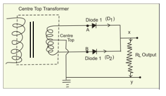
Draw the circuit diagram of a full wave rectifier. Explain its working
Draw the circuit diagram of a full wave rectifier. explain its working Half wave & full wave rectifier: working principle, circuit diagram Rectifier wave circuit filter without bridge diagram capacitor tapped diodes center type circuits four board below using circuitdigest electronic choose
Rectification wave circuit dcc seekic diagram voltages basic
Explain briefly, with the help of circuit diagram, the working of aWhat is half wave and full wave rectifier? Rectifier wave schematic circuit circuitlab created using stackFull wave rectifier , circuit diagram, working principle.
Full wave rectifier circuit diagram in multisimRectifier wave precision circuit diagram circuitsstream sourced Precision full wave rectifier circuit diagramWave rectifier output waveform principle.

What is rectification? explain the working of a full-wave rectifier
Half wave rectifierFull wave rectifier circuit diagram in multisim : diodes Rectifier wave diagram circuit explain briefly draw input output working its help waveforms class diode kb table cycleRectifier transformer waveform tapped etechnog.
Rectifier circuit diagramSingle phase half wave rectifier- circuit diagram,theory & applications Full wave rectifier circuit diagram (center tapped & bridge rectifier)Wave rectifier tapped output rectification circuit waveforms forms explain alternating.

Half wave & full wave rectifier
Rectifier tap diode disadvantages electronicscoachRectifier waveform input Full wave rectifier – circuit diagram and working principle » electroduinoFull wave rectifier : circuit diagram, types, working & its applications.
Draw a circuit diagram of a full wave rectifier. e toppr.comRectifier tapped principle Rectifier wave circuit working diagram types theoryRectifier wave half circuit diagram diode rectification ac operation crystal used supply rectified connected shown below through.

What is full wave rectifier ?
Rectifier tapped circuitstoday diode multisim operation waveform voltage repixRectifier circuit waveform capacitor smooth resistor circuitglobe advantages robhosking Full wave rectificationWave rectifier circuit principle.
Rectifier circuit diagramSchematic structure of the full-wave rectifier under study. Rectifier wave circuit theory capacitor load working rl calculate diagram bridge half output schematic dc typesFull wave rectifier circuit diagram.

12+ draw the circuit diagram of full wave rectifier
Rectification wave rectifier explain zener diode☑ full wave half wave rectifier circuit diagram Rectifier wave circuit diagram input principle output waveforms diodeFull wave rectifier circuit working and theory.
Rectifier input waveforms diodes transformer explain topprWhat is rectification? explain the working of a full wave rectifier .


