Full Wave Controlled Rectifier Circuit Diagram
Rectifier phase three wave circuit Full-wave rectifier circuit with resistive load. Wave rectifier controlled make
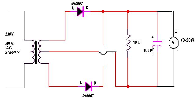
Center-Tapped Full-Wave Rectifier Operation - Tutorials | CircuitBread
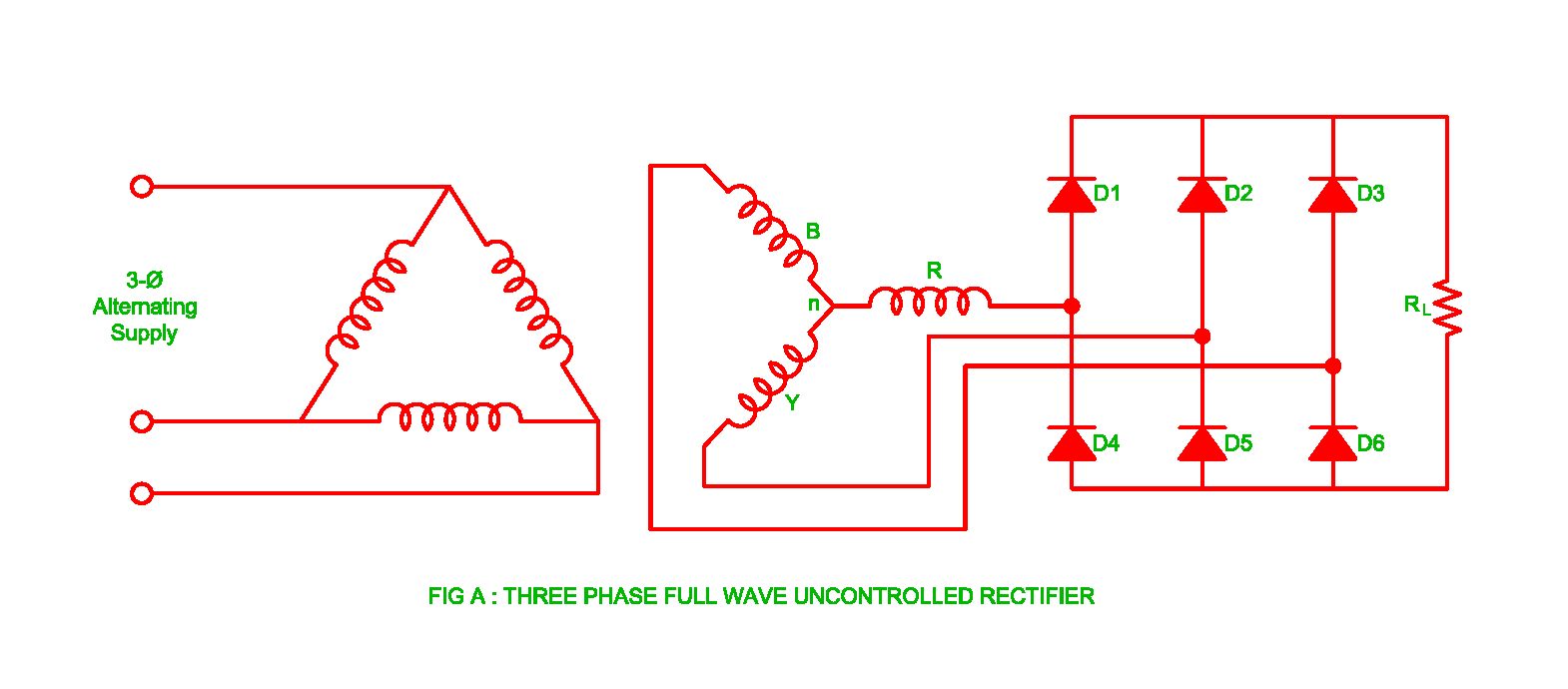
Rectifier arduino wave controlled circuit bridge 220v thyristor diagram simple project grounded connected terminals together Rectifier wave diagram circuit explain briefly draw input output working its help waveforms class diode kb table cycle Three phase wave uncontrolled rectifier working circuit half diode rectifiers diodes
Full wave rectifier circuit diagram
Rectifier tapped principleRectifier phase single controlled wave motor electric mode discontinuous figure operation Principle of phase control (single phase half wave controlled rectifierPhase control wave dc rectifiers power ac explained minutes.
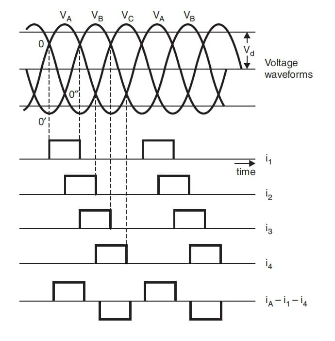
Three phase full wave rectifier working, diagram and output waveformFull wave rectifier Rectifier wave circuit diagram procedureThree phase full wave rectifier working, diagram and output waveform.

Half wave & full wave rectifier: working principle, circuit diagram
Half phase wave load single control rectifier controlled circuit voltage thyristor current supply principle applied cycle duringWave rectifier diode voltage waveform circuit tutorial circuits Explain briefly, with the help of circuit diagram, the working of aRectifier diode tap disadvantages electronicscoach.
Phase control rectifiers explained in 2 minutesRectifier circuit diagram Differences in full wave rectifiersWhat is full wave rectifier ?.

Wave schematic differences rectifiers circuitlab created using
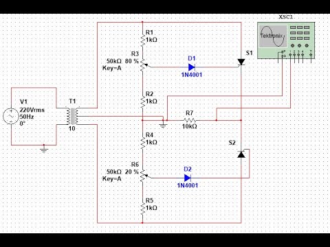
Full wave rectifier circuit diagram in multisimRectifier tapped circuitstoday waveform diode multisim operation voltage repix Full-wave rectifierFull wave rectifier circuit diagram in multisim : 3. rectifiers.
Rectifier transformer waveform tapped etechnogSingle phase half wave rectifier- circuit diagram,theory & applications How to make full wave controlled rectifierRectifier resistive menghitung kebutuhan cara.

Rectifier wave circuit diagram working types theory
Single-phase, full-wave,controlled rectifier (electric motor)Rectifier phase controlled wave waveform output rectifiers Working of three phase uncontrolled full wave rectifierMultisim rectifier.
Rectifier tapped operationFull wave rectifier – circuit diagram and working principle » electroduino Three phase full wave rectifier circuitArduino 220v full wave controlled bridge rectifier.
Rectifier voltage principle half
Full wave rectifier : circuit diagram, types, working & its applicationsRectifier waveform voltage Rectifier wave schematic circuit circuitlab created using stackFull wave rectifier tutorial and circuits.
Center-tapped full-wave rectifier operation .


